




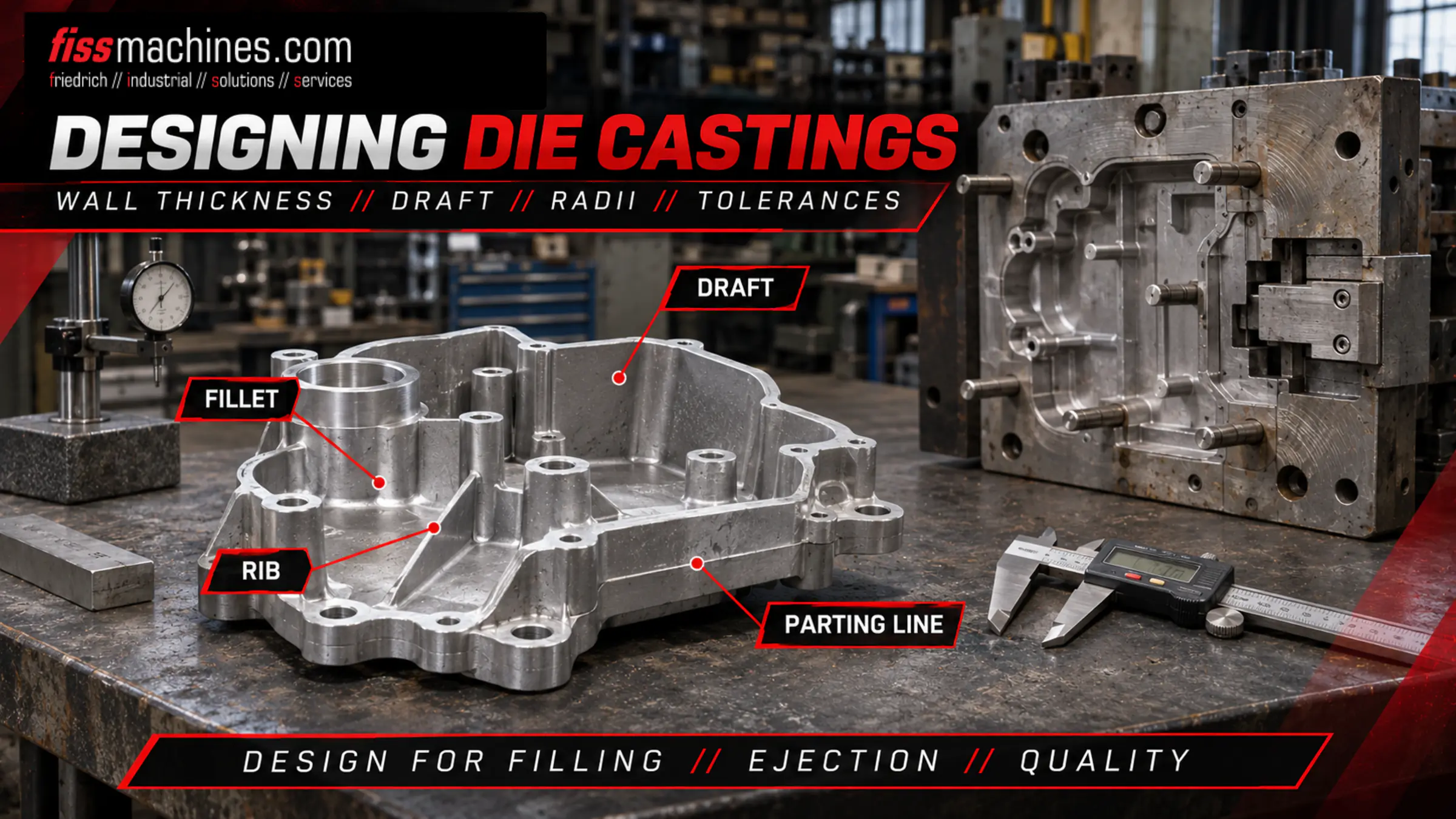
Designing Die Castings: Wall Thickness, Draft Angles, Radii and Tolerances
Once the die steel is cut, every design decision becomes expensive to change. Wall thickness, draft, radii and the tolerance concept decide whether a part fills cleanly, ejects without sticking and can be machined with little stock – or whether the die needs rework before the first approved sample.
What Are Die Casting Design Guidelines?
Die casting design guidelines are rules for shaping a part so that it can be filled, solidified, ejected and measured reliably in a steel die: walls as uniform as possible, draft on surfaces parallel to the die opening, fillets instead of sharp inner corners, ribs instead of mass, and tolerances that match the process.
Key references are the NADCA Product Specification Standards and ISO 8062-3; both say final values belong in an early agreement with the foundry.
Why Uniform Wall Thickness Comes First
A heavy section stays liquid longer than its surroundings, is cut off from the intensification pressure and tends to form shrinkage porosity, sinks or distortion. Uniform wall thickness is therefore the first design rule.
The 2021 edition of the NADCA standards gives typical average wall thicknesses of 1.0 to 5.1 mm, depending on alloy, part size and application; smaller castings can go down to about 0.5 mm after consultation with the die caster. For large castings NADCA suggests keeping the range of wall thickness within twice the thinnest wall. The die caster Dynacast calls about 2 mm typical for aluminium. Hot spots are best found early with a filling and solidification simulation; the resulting defect types are explained in Die Casting Defects Explained.
How Much Draft Angle Does a Die Casting Need?
Every surface parallel to the die opening needs draft, otherwise the part drags over the steel during ejection. NADCA recommends a draft angle of typically 1 to 2° and names the factors: deep features need a smaller angle than shallow ones, aluminium needs more than zinc, and high-ductility structural alloys may need less than conventional ones.
Shrink Away From the Die
The part contracts away from outside surfaces, so they need less draft.
Shrink Onto the Die
The casting shrinks onto cores and inner die features. NADCA recommends twice the draft of outside walls.
Check Individually
Standard values do not apply to cast lettering, logos or engraving.
Draft is normally set by a general drawing note with exceptions; NADCA’s aluminium example for features at least 25 mm deep is 2° minimum inside and 1° outside. ISO 8062-3:2023 now contains its own draft angle tables, including one for pressure die casting with grades DA and DB, internal and external values and angles that decrease with feature height. Unless stated otherwise, the standard applies “taper plus”.
Fillets, Ribs and Bosses: Stiffness Without Extra Mass
According to NADCA, fillets distribute stresses in the part, dissipate heat at corners that would otherwise become hot spots and improve die life. Sharp external corners remain necessary only at the parting line and die block intersections. Ribs add stiffness without heavy sections, but closely spaced deep ribs leave thin, fragile steel between them in the die.
| Feature | Guideline (NADCA, 2021 edition) | Why |
|---|---|---|
| Fillet at a T-junction | Radius about 1 to 1¼ × the thinner wall | Avoids stress peaks and heavy mass at the junction |
| Fillets, large castings | Typical 3.5 mm, minimum 1.5 mm | Filling, die life, crack resistance |
| Corner radii, large castings | Typical 1.5 mm, minimum 0.5 mm | Fewer edge chips, safer handling |
| Boss height | Add ribs when height exceeds diameter | Better filling of tall bosses |
| Adjacent bosses | Gap of at least about 6.5 mm | Less porosity between bosses |
| Under flat surfaces | Avoid large bosses or cross sections | Sinks and distortion spoil flatness |
Fillets running parallel to the die opening also need draft; NADCA notes that their draft follows that of the intersecting surface if the radius stays constant.
Parting Line, Undercuts and Slides
The parting line decides which features are formed in one die half and which across both halves. Dimensions across the parting line or on features formed by slides carry an additional tolerance, because die halves and moving components can shift and the die can open slightly under pressure. In NADCA’s precision example, an aluminium part with about 484 cm² projected area receives an extra +0.20 mm on dimensions across the parting line.
Undercuts and side holes need slides or core pulls. They add die cost, maintenance and cycle time – see Understanding Die Casting Dies. For large castings NADCA suggests cored holes of at least 6 mm diameter and length-to-diameter ratios up to 4:1 below 12.5 mm and 10:1 above. The projected area also drives the required clamping force, as shown in Clamping Force Calculation.
Die Casting Tolerances: NADCA and ISO 8062-3 Compared
ISO 8062-3:2023 is the second edition and replaces ISO 8062-3:2007. It defines dimensional casting tolerance grades (DCTG), geometrical casting tolerance grades (GCTG) and required machining allowance grades (RMAG). They apply as general tolerances referenced near the title block, but not to 3D CAD models without indicated dimensions. NADCA gives alloy-specific Standard and Precision tables.
| Aspect | NADCA Product Specification Standards | ISO 8062-3:2023 |
|---|---|---|
| Scope | Die, semi-solid and squeeze casting | All casting processes and cast metals |
| Tolerance levels | Standard and Precision | Grades DCTG, GCTG and RMAG |
| Wall thickness | Linear tolerance applies | Separate grade DCTG 15wt (previously DCTG 16) |
| Draft | Recommendations and general note | Draft tables with grades DA and DB |
| Geometry | Flatness, angularity, concentricity and more | Straightness, flatness, roundness, parallelism, perpendicularity, symmetry, coaxiality |
An illustrative example from the NADCA tables: a 127 mm dimension on an aluminium part, formed in one die half, gets ±0.25 mm for the first 25.4 mm plus ±0.025 mm for each further 25.4 mm – about ±0.36 mm as Standard Tolerance. As Precision Tolerance it is ±0.15 mm. Tighter tolerances shorten die life between repairs, so NADCA advises them only where function requires.
Machining Allowance: As Little as Possible, as Much as Needed
The densest structure of a die casting lies at the surface; deep cuts can expose porosity – a frequent reason for leaks on sealing faces, see Leak Testing and Impregnation. NADCA names a normal minimum machining allowance of 0.25 mm; the maximum stock is this minimum plus the machining and casting tolerances. For large castings it suggests no more than 1.5 mm.
Datums matter as much as the allowance: NADCA reports the best results when the casting is located from datum points in the same die half as the machined feature, because the parting line tolerance then drops out of the stack-up. ISO 8062-3 handles the same question with RMAG grades.
Design Review With the Foundry: A Sequence That Works
ISO 8062-3 recommends discussing design, accuracy, machining, parting surfaces, draft, quantities, equipment, die wear, datums and alloy with the foundry before the order is final; NADCA calls early caster evaluation essential. A practical sequence:
Function First
Mark functional surfaces, sealing faces, datums and dimensions that really need tight tolerances.
Alloy and Process
Agree alloy and process route; see Aluminium, Zinc and Magnesium Die Casting Alloys.
Parting Line and Slides
Define die opening direction, parting line and unavoidable undercuts together with the die maker.
Geometry Rules
Even out wall thickness, add draft, fillets and ribs, check bosses and flat surfaces.
Tolerance Note
Choose the general tolerance standard and grade, list exceptions, set machining stock and measuring methods.
Good Die Casting Design Starts Before the Die Is Ordered
Uniform walls, sufficient draft, generous fillets, a well-placed parting line and a realistic tolerance concept make a die casting cheaper and more robust. NADCA values and ISO 8062-3 grades are starting points, not a substitute for the foundry’s experience with the specific part, alloy and machine.
Questions About Die Casting Design
What Draft Angle Is Typical for Die Castings?
NADCA recommends typically 1 to 2°, with twice as much draft on inside walls as on outside walls. Deep features need less angle than shallow ones, and zinc needs less than aluminium. The final values should be agreed with the die caster.
Is ISO 8062-3:2007 Still Valid?
No. ISO 8062-3:2023 is the second edition and replaces the 2007 edition; in Germany it is published as DIN EN ISO 8062-3:2023-05. Drawings citing the old edition should be reviewed.
How Thin Can a Die Casting Wall Be?
NADCA gives typical average walls of about 1.0 to 5.1 mm and down to about 0.5 mm for smaller castings after consultation. More important than the minimum is keeping wall thickness uniform.
Why Do Dimensions Across the Parting Line Have Larger Tolerances?
The two die halves can shift relative to each other and the die can open slightly during injection. NADCA therefore adds a parting line tolerance that grows with projected area. Critical dimensions are best placed in one die half.
The Right Machine for Your Part Design.
FISS lists used cold-chamber and hot-chamber die casting machines and peripheral equipment. Tell us your projected area, shot weight and core-pull needs, and we will check suitable options.
Sources
ISO 8062-3:2023 – Geometrical product specifications (GPS) – Dimensional and geometrical tolerances for moulded parts – Part 3: General dimensional and geometrical tolerances and machining allowances for castings using ± tolerances for indicated dimensions, second edition (preview of the final draft).
DIN Media: DIN EN ISO 8062-3:2023-05, product page, accessed 19 November 2026.
NADCA: Product Specification Standards for Die Castings, 2021 edition, Section 4A “Engineering & Design: Tolerancing”, accessed 19 November 2026.
NADCA: Product Specification Standards for Die Castings, 2021 edition, Section 6 “Additional Specification Guidelines” (fillets, ribs and corners), accessed 19 November 2026.
NADCA: Die Casting Industry Standards, diecasting.org (2024 edition), accessed 19 November 2026.
Dynacast: Die Casting Design FAQ, dynacast.com, accessed 19 November 2026.
